

What are the advantages of an electric float gauge?
1. Ease of manufacture
2. Independence of the indication relative to the variations of the aircraft power system if the measurement is made by a ratiometer
3. Independence of the indication relative to the variations of the aircraft power system if the measurement is made by a galvanometer
4. Independence of the indication relative to temperature variations
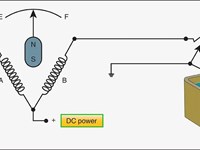
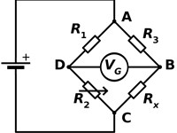
Refer to figures.
The electrical-type quantity gauge consists of an indicator in the cockpit and a float operated transmitter installed in the tank. The transmitter sends a different level of signal to the cockpit, dependent on the height of the float in the tank, and the signal then feeds the indicator.
This type of systems are simple and cheap to manufacture and some systems can be isolated from changing voltages in the aircraft electrical system. Other advantages of this fuel quantity gauge include:
- an indicator which can be located any distance from the tank; and
- the fuel levels of several tanks can be read on one indicator.
The disadvantage of float type fuel gauges is that they are always subject to variations in temperature, measuring volume, not mass of fuel.
The two primary ways of making an electric type float gauge are with a ratiometer and a wheatstone bridge (galvanometer).
The ratiometer works as seen in the first figure above. The DC power is sent equally through two circuits, one circuit with a fixed resistor, and the other with a variable resistor connected to the float in the tank. Each circuit has a coil of wire on it to produce a magnetic field, and the magnetised needle sits between, pointing to a position on the dial dependent on the relative strength of the magnetic fields, which will change based on the resistance of the variable resistor (and therefore the height of the float gauge).
This indication does not vary with changes in system voltage, as it is measuring relative magnetic fields from the same source (useful as aircraft system voltages vary).
The wheatstone bridge (galvanometer) system, seen in the second figure above, instead measures the resistance of the same variable resistor (connected to the float) by splitting the current of the circuit between two paths, one path having 2 fixed resistors, and the other path having a fixed resistor and the variable resistor. The variable resistor then changes how the resistance is split amongst that circuit, and current will want to flow through the galvanometer in the middle either one way or the other (and by a certain amount). A galvanometer is a very precise ammeter for our purposes.
This indication does vary with changes in system voltage in a linear sense (higher voltage = higher indication), so is less useful than the ratiometer.
Your Notes (not visible to others)
This question has appeared on the real examination, you can find the related countries below.
-
United Kingdom2
-
Finland1
-
Latvia1


 Use Keyboard Shortcuts
